Exploring ESP-8266 and other electronics as a beginner
To preface, I've done a little electronics before and embedded programming with an Arduino kit. Just the basics, turning on some LEDs, using buttons and other modules in the starter kit. But, I decided that if I'm going to make lots of little projects, I'd have to find a cheaper and more sustainable way since the Arduino boards are quite expensive. That's where these ESP boards come in, they're only about £1.50 from AliExpress and even cheaper in bulk, they have decent performance, Wi-Fi and a lot of output pins. Seems like a good place to start.
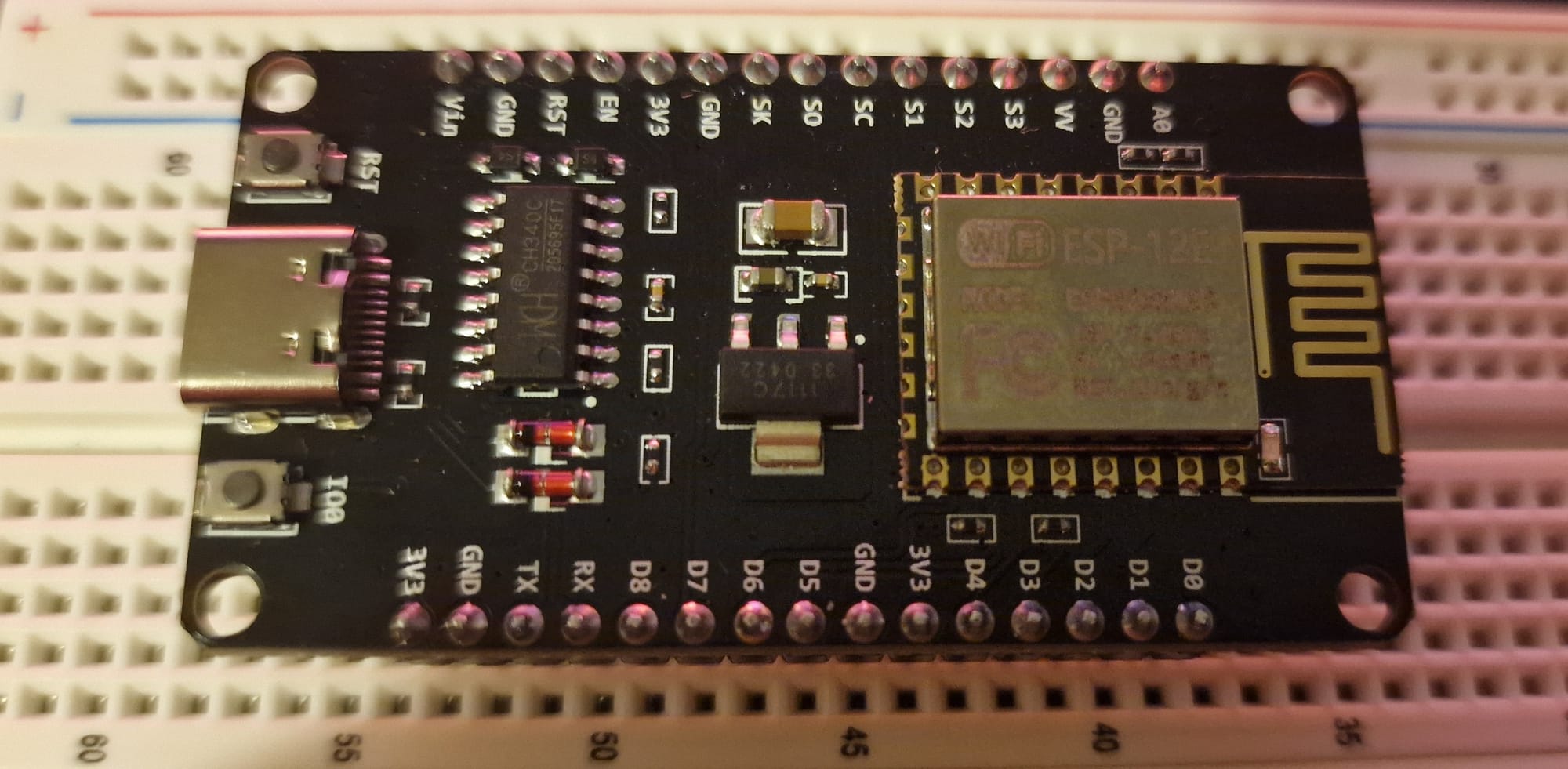
I bought a few of these ESP-8266 boards to play around with:
I then tried to set it up with Clion as JetBrains products are what I am the most comfortable with, however this turned out to be incredibly complicated and way beyond my knowledge. Maybe something to try next time, since I would really like some proper intellisense and project management. I got pretty frustrated trying to figure out how to get this setup, so I left it for the day.
I went back to the Arduino IDE the next day and it's far easier. I just installed the package for my board model and loaded some examples onto it, nice and easy. I checked out some of the examples, and I've got to be honest, this is VERY cool, really impressive the stuff that it can achieve. Like just being able to scan Wi-Fi networks nearby and having a mini web server running from this tiny £1.50 board is seriously fun.
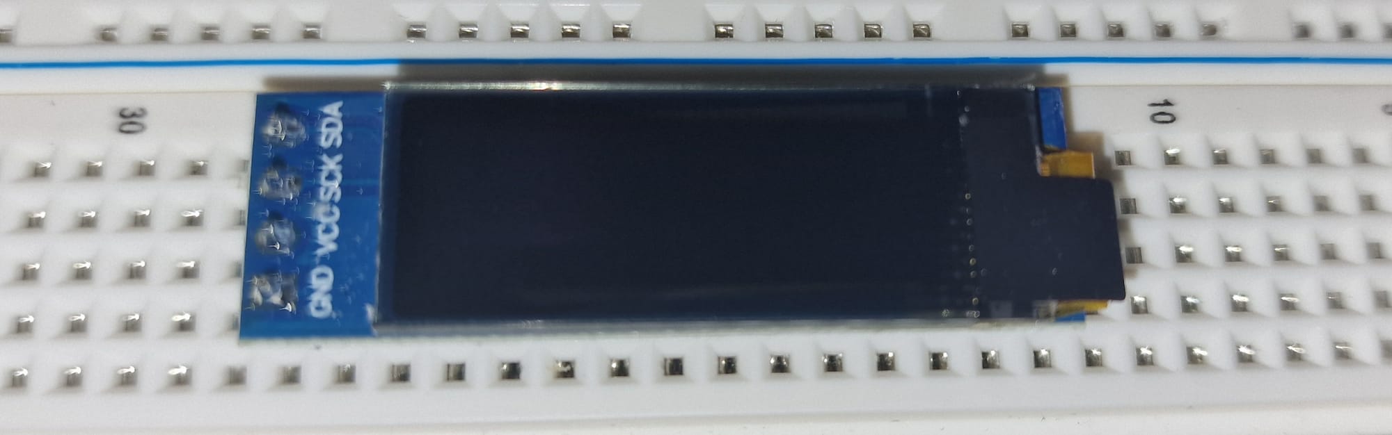
The goal from here after is to achieve a basic setup and get into the more electronic side of things. I have a tiny OLED screen that I want to hook up via a breadboard and try to output some text to it. Maybe the Wi-Fi networks that I'm scanning?
Later on, I want to order a charging circuit board for 3.7 V 500 mAh batteries that I scavenged from discarded disposable vapes. These batteries are lithium-based, so they should be rechargeable; however, you can't just wire them up to a USB charger and start charging, unless you want to set the fire alarm off. So a charging circuit to regulate power in and out, shut off, and some other fancy stuff is needed. Since I'm not currently planning to wire these batteries in series to make a bigger capacity and voltage, I don't believe I'll need any other circuits. So it should be fine to just wire up the single cell to this charging circuit. Then, the idea is to get a USB-C board and use that to power the ESP-8266 over USB-C too. Making it a little more modular. I could also just directly hard solder it to the board as well for power and make it a combined unit. This setup will require me to order some more parts from AliExpress, and it took a few weeks for the original pieces to come, but I'll order them sometime this week and go from there.
I am very excited to get soldering, too. I want to practice it and get better at it. Not only that, but I was thinking of taking apart my old broken printer and using it as soldering practice, as well as salvaging parts from it (although I think it's far easier to just order the parts I need directly, there's a certain purifying feeling in my soul that I know I'll just get from recycling and scavenging parts from something that is on the verge of going down the toilet).
I have to admit, I was quite frustrated and losing patience with trying to set up this ESP8266 board with CLion. I've never programmed in C, so I'm very unfamiliar with compilers and the process to get it working. Thankfully, Arduino IDE was extremely easy to get working compared to it, so I'll just have to stick with it.
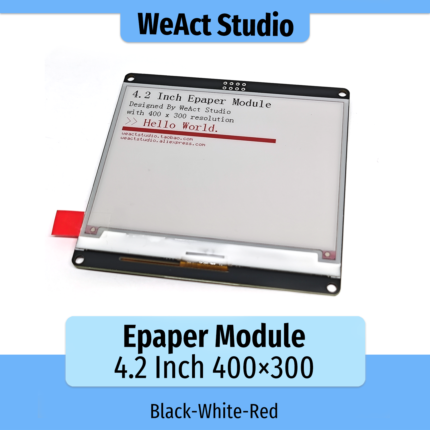
So, I went a bit overboard and ordered some more cool things. Today, one of them arrived. A red, Black, and White 4.2-inch e-paper module from WeAct Studio. I got it from AliExpress here for about £15, including delivery. Took a good while to come.
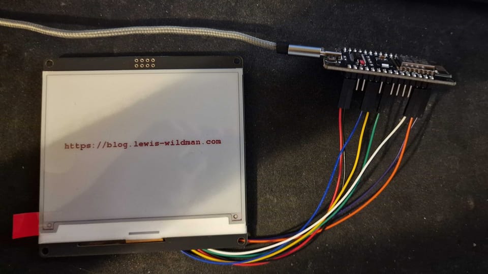
It was pretty easy to get up and running. The company had a GitHub link for documentation and some examples. So I used that and managed to get a cool output using my ESP8266 board. I had to find a diagram online on how to wire it up because I'm not really sure of what most of the pins on the ESP board actually do aside from the ground and 3.3v pin. (Which is exactly what this e-ink display takes, luckily!)
Here's what I managed to output after a bit of trial and error. I was very excited.

Originally I used the wrong screen size drivers, and I got a very funky and weird-looking output, but eventually I got here with the correct orientation.
This is cool and all, but now I want to take it further, and my next plan is to use the onboard Wi-Fi from the ESP, connect to my home connection, and then try to pull some data from an API on my site and display it. Have it refreshed every x amount of time.
The display can also output shapes too, so I may build a simple UI too. However, I also ordered a credit card-sized keyboard for this display too, as my ultimate goal is to build a little Nintendo DS-looking device that can store some text files. Although I'm not sure if the ESP can handle that, I'll probably need some kind of storage module that can take a microSD card. But that's a long way down the line. I still need to figure out how to make more scalable applications since, at the moment, I'm not even sure how to link multiple files together; all I've been doing is writing 1-file scripts.
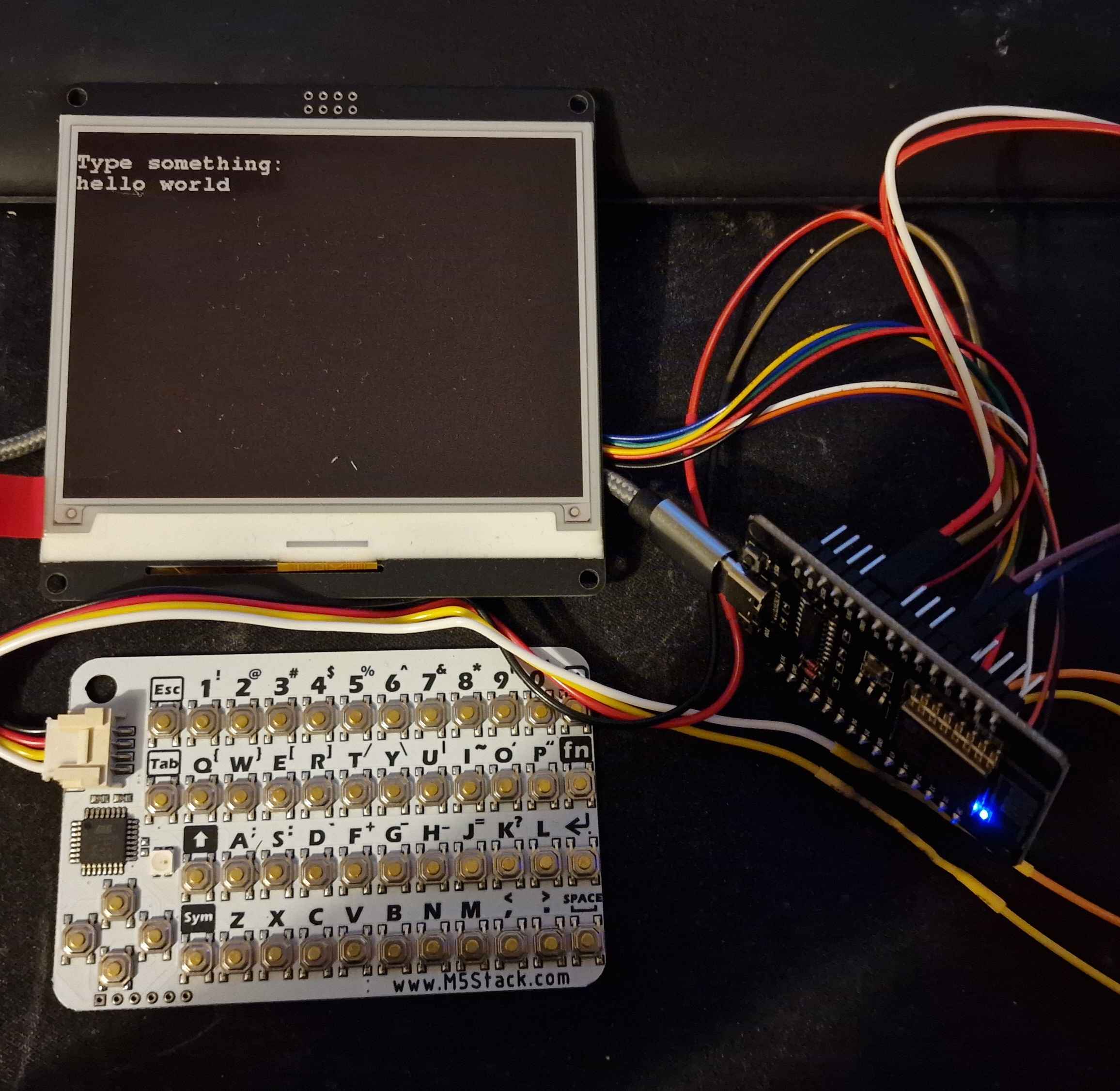
So, the keypad and a couple of more advanced pieces came today, many of which requiring some soldering (which I've discovered I am utterly horrific at, I couldn't even solder pads for an electric guitar). So I thought I'd start with the keypad and try to get that hooked up. Now, I couldn't find any documentation for this, so I had to entirely just rely on ChatGPT for this just to at the very least get the wiring hooked up and get the serial data popped through. Which it seemed to be able to do, great.
Next was to write a basic typing system and output it. Which, with each key press, I just updated the screen to show the new letter being output. HOWEVER, here's where I ran into a massive issue, the screen took 7 seconds to refresh EACH time!!! Not exactly a responsive user experience I am looking for, so I'll partially refresh the area where the text will be updated, and so I did. Pressed the key again and 7 seconds later, it updates...
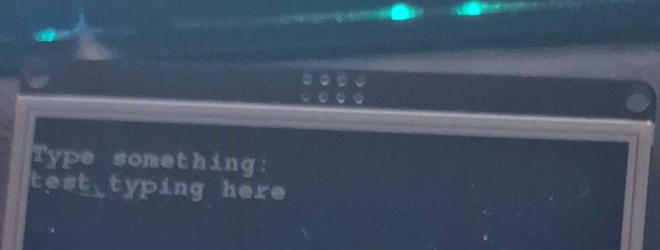
Not ideal, it turns out that because my screen is RED/BLACK/WHITE, it doesn't support partial refreshing, or at least as far as I could find out about it. So until I find a solution for that, I just buffered the characters being typed so it only refreshes the screen if you press enter or 4 seconds have passed by. Here's the end result!
So, after looking around with the display I have, I truly don't believe I can't partially update it and make text output faster. So I found this video and in the first few seconds he mentions that he also has a 3 colour display.
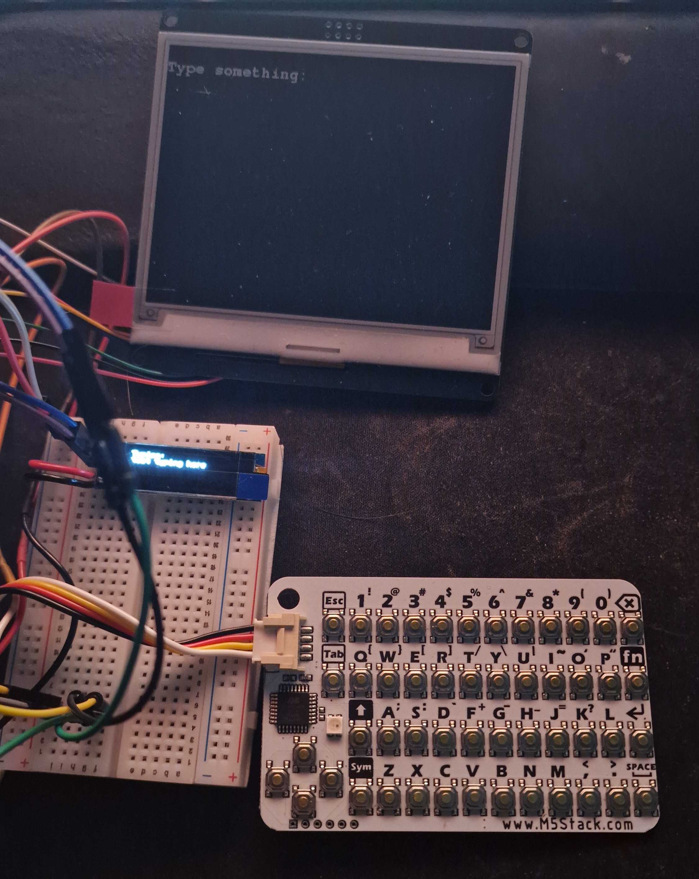
I gave this a shot but couldn't get the same results, my display just kept fully refreshing. Not sure if I need to get the black/white model only for partial refreshes to work. But I have another idea, I have the mini 0.9" OLED screens I mentioned before, so my plan now is to use that as a typing bar to instantly display what is being typed, then once the typing buffer is confirmed the OLED screen is wiped and the results are sent to the main screen. Because why not?
I ran into an issue where I began to run out of data pins, however, since the keyboard and OLED screen both use I²C as a serial bus, I was able to send data over the same wire to the same pin without needing more.
This allowed me to set up the OLED screen and get a small typing bar to pre-see what is then committed to the main screen.
And then after pressing enter, it gets updated to the main screen!
What's next?
The next step for me is to build something more permanent. And I think a good project for that is a weather/clock and information display panel. I'm quite excited to build something and complete it, since a lot of the electronic stuff I've done so far has just be very questionable looking prototypes.
Epologue
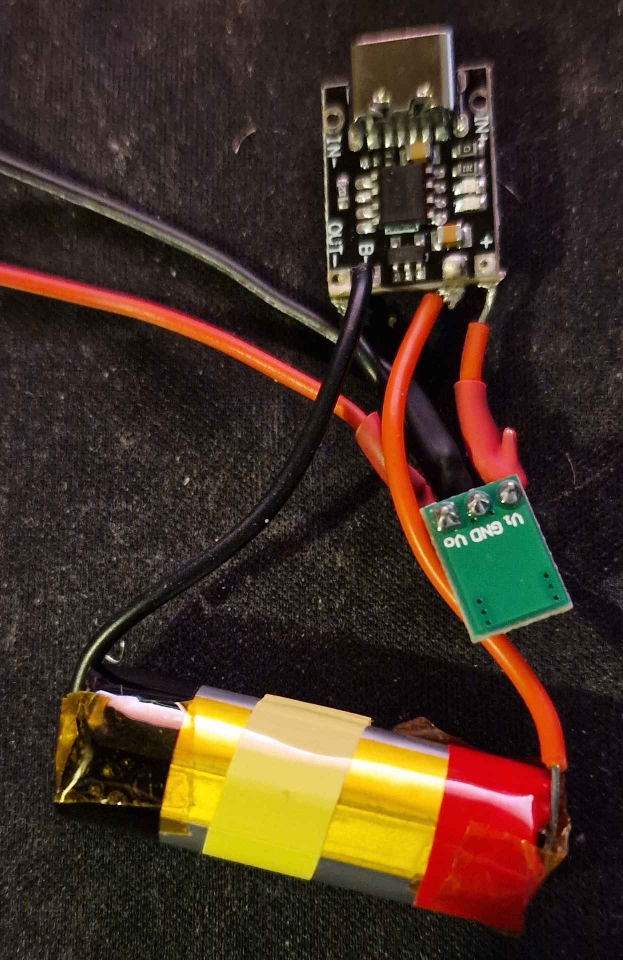
So before I took this project apart I wanted to attempt something that I had been planning for a while and that was to make a rechargeable USB c compatible battery from vapes. But it didn't go too well, and I only have 1 picture of the aftermath.
Essentially, I was trying to measure the amperage of the charging over this battery I had built. The charging board was outputting 1A, but my lithium battery was only 500mah, so I wanted to put a 10omh resister on it just to see if it would drop the charging down. However, I must've done something wrong because I blew a fuse on the charging circuit itself trying to measure it. I got spooked and just ripped the whole thing off the battery to make sure I didn't burn anything. I also blew a fuse in my multimeter too so I've had to order a pack of fuses for the thing. But I did learn a lot doing this little project, and hopefully I'll make something much better next time. I also started getting the gist of soldering too, before I would struggle quite badly, but I made a decent amount of solders during this. Albeit they were absolutely awful solders, it did work.
The idea is that any USB c charger would go into the circuit, the circuit would regulate the voltage and make sure that it charged the battery safely and correctly to the right voltage and then stop. Then, the output from the charger circuit would go into the green buck circuit converting the output of 4.2v to 3.3v which was exactly what I needed for my ESP-8266. And, for a time, it was working great. It charged nicely, discharged nicely (nice) and powered my esp perfectly. I just looked into it more and realised that it could kill the battery or cause a fire since I was putting 2x the amount of supported amperage into the battery, so, slowing it down with a resistor between the charger circuit B+ to the battery positive was the aim here. But again, blew a fuse or something (not even sure what) during testing because I had a hard time holding the wires together and whatnot. I believe the issue here was just me short-circuiting something with my fiddly hands holding the multimeter. BUT, I did get far with this whole thing, and it makes me excited to try new things.
I think if I attempt this again I may wire up 2 of these 500mah batteries in parallel so that way I can have 1A charging without the need for any resistors, and have twice the battery capacity. Not sure how I'll do that, but we'll see. I'm surprised how far I made it with just the help of ChatGPT.
Anyway, thanks for reading, hope you enjoyed it! Be sure to comment any suggestions, especially regarding the rechargeable battery!
Member discussion